Monday, September 27, 2010

Thermo Fan Switch (T.F.S)


The thermo fan switch is also a thermistor.
This one in particular is NTC.
It has semi-conductive properties which causes its resistance to decrease as the temperature increases; as explained in the ECT post.

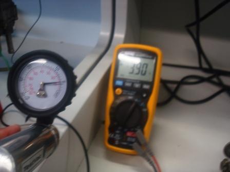
Suspend the thermo fan switch in a container of water and record the results.


As you can see in the graph, the resistance is at its highest when the TFS is cold, and gradually the resistance decreases as the temperature gets hotter.

Note at approximately 98 degrees Celsius, the resistance is so low that it goes "OL".
When this occurs, the semi-conductive materials in the thermistor are allowing more electricity to flow freely, so that there is no resistance.
Therefore, the circuit can be complete by electricity flowing freely without any resistive opposition. The switch is on, and it works fine.


Coolant Temp. Sensor (CTS)/ Thermistor Water (THw)/ Engine Coolant Temp. (E.C.T)

A coolant temperature sensor is also known as a water thermistor.
Thermistor is a combination of two words, "thermal" & "resistor".

The engine coolant temperature sensor (ECT) monitors the heat of the coolant, and the ECU uses this data to keep the engine running at optimum performance whether the engine is running cold or hot.

Suspend the ECT sensor in a container of water and record the results.


This is a NTC type thermistor.
The experiment starts with the ECT's resistance at approx. 3kΩ at room temperature 15 degrees celcius, and gradually decreases to approx. 662Ω when the temperature increases to 60 degrees Celsius.
The semi-conductive materials used in these thermistors (such as nickel, cobalt, oxidised copper etc.) are resistive to the flow of electricity passing through the electrodes. As the temperature increases, these certain elements characteristically "shrink" or allow electricity to pass more freely within the thermistor.
This ECT appears to work as it should.


Air Flow Meter / Vane or Flap air flow sensor (A.F.M)


A Vane/Flap air flow sensor/meter (A.F.M) basically serves the same purpose as a M.A.F. sensor; Although earlier German and some Japanese manufacturers preferred this method of air flow monitoring.

It's internal function is also similar to that of a T.P.S.

The A.F.M is located on the vehicle's air intake system before the throttle. Instead of having a throttle butterfly like a T.P.S, it has a spring loaded mechanical flap that opens and shuts proportionally to the amount of air entering the engine.
The flap has a wiper arm that rotates against a variable resistor or potentiometer. So the more air flowing in, the further the vane flap is forced in. The wiper arm rotating against the potentiometer causes the resistance to increase, or decrease depending if it is NTC, and therefore the Voltage input signal will increase or decrease accordingly with the resistance readings.


The readings that the A.F.M and other sensors collect will let the ECU know how much fuel etc will be needed.

Mass Air Flow Sensor (M.A.F)


An air flow mass sensor has a platinum hot wire in the vent that stays hot at a certain temperature. When air passes through the vent it will cool down the hotwire, so more current is put through the wire to maintain its set temperature.

The amount of current put through to the platinum wire will calculate how much air mass is flowing through the vent.


What voltage did you get when you first powered up the sensor without passing air over the sensors?
1.048v


How did the voltage change when air passed over the sensor?
Increases proportionally according to how much air passes through.


Wednesday, September 22, 2010

Manifold Absolute Pressure (M.A.P) Sensors


MAP sensors are very similar to MAF sensors.
It monitors vacuum pressure in the intake manifold according to engine load, and the ECU uses the data it collects to adjust ignition timing and fuel enrichment.

When the throttle is wide open (like when accelerating), the pressure in the intake manifold is at atmospheric pressure, or Lambda 1. So there is no pressure. The ECU will then give a rich fuel mixture to help combust more air. Likewise when the throttle is closed (like when the engine is idling), there will be more pressure in the intake manifold, so the ECU will respond with a leaner fuel mixture.


Wire up a MAP sensor with a 5v feed and earth. Measure the return voltage from the third wire. Using a miti-vac apply vacuum to the MAP sensor. Plot the voltage return in relation to the vacuum applied.


The voltage on this MAP sensor is high when the pressure is high in the manifold. It decreases as the vacuum pressure is dispursed. This indicates that the MAP sensor is working fine.

Monday, August 30, 2010

Throttle Position Sensor

What type of Throttle Position Sensor is this?


Variable TPS


Explain its internal operation and why your voltage changes

A Throttle Position Sensor on a motorvehicle is usually found along the air intake system. It is usually mounted directly onto the spindle, and monitors the position of the throttle butterfly.
This variable type throttle position sensor has a variable resistor. It has a 5v supply that is used by the ECU to determine the throttle position via signal output.
The voltage will vary according to the butterfly position.
If it is in wide open throttle (w.o.t) the voltage will be approximately 5v.


When it is in idle, it would be closer to 0v.


Now connect a Power Supply to your sensor and test the voltage ouput at different throttle angles.


From the above graphs you can see just how the voltage increases when the throttle is opened.


Testing the TPS.


Results of the TPS test:


The resistance across the TPS increases as the throttle opens, this is because the voltage increases also.
The TPS has a carbon strip and stylus. When the throttle opens, the stylus (which is connected directly to the throttle butterfly spindle) moves up the carbon strip. When it is at W.O.T, the voltage will be approximately 5v, and the resistance will be approximately 3 ohms.
When the throttle butterfly is shut, the stylus will move back down to the bottom, and have about 0v, and O.L resistance.