Monday, September 27, 2010

Hall-Effect Sensors


Hall effect sensors and probes are components which use magnetism to calculate equations and in automotive applications, includes sensing camshaft position and TDC.
It was invented by physicist Edwin H. Hall in 1879.

A Hall effect sensor has a Hall integrated I.C, which corresponds with a magnet. It also has a steel chopper plate with recess gaps that interrupts the magnetic field built up from the Hall integrated I.C and the magnet.


Wire up the distributor. Connect an oscilliscope then spin the distributor and observe the waveform.


Above is an oscilloscope pattern drawing of a hall effect sensor.
It is a square wave pattern.

1. The dwell period - Duty and firing time combined.
2. The duty cycle period - When the chopper plate is passing in front of the IC and the magnet, strengthening the magnetic field and increasing the voltage as it passes by.
3. The firing time - When the recess in the chopper plate passes in between of the I.C and magnet.
4. The peak voltage which is produced

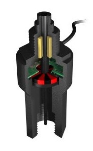
Speed or Position Sensors


This speed sensor has a magnet, an electric circuit board, and a hall element.


1. Is static/A.C magnetism around the environment.

2. The voltage spike that is induced as a magnetic field from the reluctor comes into closer contact with the steel poles.

3. As the reluctor points get farther away from the steel poles the magnetism decreases & voltage decreases too.

The shape of the wave form is also a good indicator of what the shape of the reluctors teeth are like.

Oxygen Sensor (O2 Sensor)


The vehicle's Oxygen sensor (O2 Sensor) or lambda sensor can be found along the exhaust line.

As seen on the experiment, when the flame is on the sensor, there is no oxygen passing the sensor, and the voltage is up.
As soon as the flame is off, the voltage drops.

Knock Sensor


A Knock Sensor is usually mounted to the vehicle's engine, near the combustion chamber so it can detect knocking, or "pre-detonation".
The sound of the knocking can be described as a marbel hitting metal, and it can damage the inside of the engine, including valves, pistons, rods and more.


When the air fuel ratio detonates early, instead of combusting at the proper point of ignition; this produces a knocking sound. The knock sensor commonly has a "piezo crystal" which vibrates as a reaction to the knock pressure waves, and its vibration induces an electrical signal. Thats why you dont have to supply any voltage to it


Connect the knock sensor to an oscilliscope.
Gently tap the knock sensor and observe the waveform.


Intake Air Temp. Sensor (I.A.T)/ Air Temp. Sensor (I.A.T) / Thermistor Air (THa)


The Intake Air Temperature sensor is also a thermistor, and is also known as a "thermistor air" (THa).
Its located along the air intake system, and its internal workings are very similar to those of the other thermistors.

Connect an ohmmeter to the terminals of the sensor. Suspend the sensor in a container of water and heat. Report your results.


This thermistor is also working fine.
The lower the temperature, the higher the resistance. The higher the temperature, the lower the resistance.

Thermo Fan Switch (T.F.S)


The thermo fan switch is also a thermistor.
This one in particular is NTC.
It has semi-conductive properties which causes its resistance to decrease as the temperature increases; as explained in the ECT post.

Suspend the thermo fan switch in a container of water and record the results.


As you can see in the graph, the resistance is at its highest when the TFS is cold, and gradually the resistance decreases as the temperature gets hotter.

Note at approximately 98 degrees Celsius, the resistance is so low that it goes "OL".
When this occurs, the semi-conductive materials in the thermistor are allowing more electricity to flow freely, so that there is no resistance.
Therefore, the circuit can be complete by electricity flowing freely without any resistive opposition. The switch is on, and it works fine.


Coolant Temp. Sensor (CTS)/ Thermistor Water (THw)/ Engine Coolant Temp. (E.C.T)

A coolant temperature sensor is also known as a water thermistor.
Thermistor is a combination of two words, "thermal" & "resistor".

The engine coolant temperature sensor (ECT) monitors the heat of the coolant, and the ECU uses this data to keep the engine running at optimum performance whether the engine is running cold or hot.

Suspend the ECT sensor in a container of water and record the results.


This is a NTC type thermistor.
The experiment starts with the ECT's resistance at approx. 3kΩ at room temperature 15 degrees celcius, and gradually decreases to approx. 662Ω when the temperature increases to 60 degrees Celsius.
The semi-conductive materials used in these thermistors (such as nickel, cobalt, oxidised copper etc.) are resistive to the flow of electricity passing through the electrodes. As the temperature increases, these certain elements characteristically "shrink" or allow electricity to pass more freely within the thermistor.
This ECT appears to work as it should.