Thursday, October 7, 2010

WS8 Primary & Secondary ignition patterns


WS7 Exhaust gas analysis (petrol only)


1999 Mazda Capella

1. What are the 4 gas readings with the analyser probe sensing normal air?


Results indicate the air is quite clean, and can only read a high rate of oxygen, and a small amount of H.C.

2. What are the 4 gas readings while the engine is idling cold?


As the engine is cold, it needs to run a rich mixture because the air in the engine is still cold and dense, but because the fuel ratio is very high, the partially burnt fuel is emitted as Hydrocarbons (HC).
Because of the lack of O2, the Hydrogen is easier burnt off from the HC, and the Carbon particles which remain need to bond to something, so it bonds to the Oxygen particles, which cause a higher percentage of carbon monoxide (CO) which is deadly if someone inhales approximately 0.03% CO.
CO2 percentage is up too, since some of the O2 and C particles have bonded with each other. CO2 is more desirable than HC or CO since it isn't as harmful.

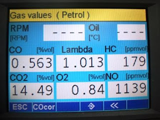
3. What are the gas readings when the engine has warmed up?


When the engine has warmed up a bit, the CO levels have come down a lot, also HC & CO2 levels are down, and O2 is up. This is because the engine is running a leaner fuel mixture now because the air is no longer dense or cold. Because the engine has appropriate heat, not as much fuel is required, so total emissions have decreased.

4. What are the gas readings when the engine is warm, and run at 2500 RPM?


When doing this, the vehicle is running more richer than at warm idle.
The HC is still low, thats because there isnt so much unburned fuel, but CO & CO2 are high while the O2 reading is extremely low. That is because the engine is running at a moderately rich mixture.

5. At idle run the mixture rich with extra propane, LPG or carburettor cleaner, and record the gas readings.


By spraying carb cleaner into the air filter it enriched the air/fuel mixture.
The HC is down surprisingly, but it means that its being burnt efficiently.
CO is down also because there isnt so much HC being burnt improperly, and the catalytic
converter is doing its job correctly.
CO2 & O2 is still up a bit. This is good, it shows that the engine is running efficiently when running a rich mixture.

6. At idle create a lean condition with an air leak or vacuum leak. Record the gas readings.


As the air leak was created, the HC went high. This was caused to the air/fuel ratio being incorrect. There wasnt enough air to help the fuel burn more efficiently.
The CO2 went down slightly, and the O2 went slightly higher along with the CO. The CO is becoming higher because, the engine is running more leaner.

7. Accelerate the engine, by blipping the throttle a few times and watch how the gas readings change.

CO: 4.253%
HC: 110ppm
CO2: 5.72%
O2: 8.17%

CO becomes extremely high yet the HC drops. This indicates that the engine is running a very rich mixture, yet is combusting properly. Cat converter is also working properly.

8. Disconnect one spark plug wire, ground it with a jumper wire, then record the gas readings as the engine idles.


HC is extremely high. This is because there is a misfire, and the air/fuel ratio isnt combusting properly. This misfire also causes the CO to increase because the Hydrogen particles are being burnt off leaving a volatile Carbon particle to bond to an oxygen particle becoming CO.
The O2 is also now higher than the CO2 reading, because the amount of unburned fuel is increasing the need for O2.
When the CO2 is high, and the rest are lower, it generally means that the engine is running efficiently. So since the CO2 is low here, it proves there is something wrong in the engine; the spark plug misfire.

9. disconnect the injector harness connector from one injector, and record the gas readings as the engine idles.


Disconnecting the injector harness made the HC, CO and O2 moderately increase.
and CO2 decrease. This is because the engine is running rich, and there is a misfire.

10. At idle, measure the gas readings while air conditioning is on and rocking the steering wheel.


All readings are acceptable, and not much wrong with it apart from a decrease in O2 and an increase in CO. This is because the air con is causing the engine to run slightly richer.
The extra emissions caused by having the air con running and rocking the steering wheel is minimal.

WS6 Oxygen sensor on vehicle


1999 Mazda Capella

The O2 sensor is located in the engine bay just on the exhaust manifold outlet.
It is a zirconia switching sensor and it has 3 wires:
1. Power - White
2. Ground - Grey
3. O2 signal

After back probing the the signal wire and connecting an oscilloscope, I got an ok signal.

I revved the engine at 2500rpm for about a minute so it would go into closed loop.
This is the pattern that I got.


Peak voltage is 0.8v and lowest voltage is 0.2v. So average voltage would be 0.5v.

Cross counts the signal has in 10 seconds is 10. So it is cycling normally.

Let the engine warm up and enter closed loop so you see a normal cycling pattern. Let the RPM come down to idle.


Highest voltage: 0.8v
Lowest voltage: 0.2v
Average voltage: 0.5v
Cross counts in 10 seconds: 8
Signal status: Cycling normally


Rev up engine so it goes rich. Record results. The signal should go above 0.85v.


Highest voltage: 1v
Signal status: Cycling normally

Make this sensor go lean. Rev up the engine then suddenly decelerate. The signal should go below 0.2v.


Lowest voltage: 0v
Signal status: Cycling normally

Measure the response time. Time how long it takes to go from lean to rich. Voltage should go from below 0.2v to above 0.8v in less than 100ms.


Time: 60ms
Status: slightly slow.

O2 sensors are one of the most important signals on a vehicle. Without it, your vehicle could be running inefficiently and uneconomically, and could cause the engine to fault since the ECU would be missing out on a lot of important data to ensure the vehicle is running in optimum condition.
Zirconia switch sensors are more common since they are cheaper to manufacture. They also switch fast and can withstand high temperatures.
When rich O2 ions from exhaust pass through the sensor, electrons start to flow so you get a higher voltage.


WS5 Scan tool diagnostics


1999 Mazda Capella


No faults were indicated by the scan tool, so faults were created by Lecturer Steve.

After faults were created; vehicle was scanned again.
New faults were found as follows:


Comparing the value data before and after the faults:
-IAT temperature was originally 24.21, now 19.85 degrees Celsius
-MAF voltage was originally 1.88v, now 0.00 volts

When inspecting the engine bay, the IAT and MAF sensors were found loose or unplugged.

Both sensors were reconnected.

Scan tool was used again after sensors were reconnected, and these are the results.


The readings returned to normal.
Without knowing these parameters, it is possible to not know if there were any faults at all since the scan tool doesnt always pick up the faults. But by comparing the data from the different parameters, it is possible to find a fault if the scan tool doesnt pick any up.

WS4 Fuel Pressure and flow (petrol only)


Attach fuel gauge, briefly turn on key then turn it off. Check for fuel leaks.
No leaks.

Measure the fuel pressure with the key on, engine off.
284 kpa

Measure the fuel pressure engine edling. Watch the pressure for a couple minutes.
260kpa

When idling, use special tool to clamp the fuel return line.
500kpa

When idling, disconnect and plug the vacuum line to fuel pressure regulator.
300kpa

Turn off engine and watch the fuel pressure for 5 mins. Record residual.
250kpa

Read fuel volume. Record volume pumped in 15 seconds. Normal results around half a litre.
2.2 litres in 15 seconds

Its important to know the vehicles fuel pressure/flow so that you know whether the car is running at its optimum condition. Otherwise a faulty fuel pressure regulator maybe sending incorrect data to the ECU, and in turn several faults may incur in your vehicle. i.e: engine constantly running rich, or combustion chamber being flooded with gas. Emissions would be extremely high.

WS3B


WS3A Lab scope

Engine: Toyota 4A-FE
Signal name: Crankshaft Position Sensor
Volt/division/range: 2v
Time/division/range: 20ms
1. At this point, the sensor is directly in between the crank teeth giving a neutral magnetic force, and thus reading 0v.

2.As the next crank tooth approaches, the magnetic field starts to get stronger again, so the voltage reading starts to get stronger.

3. At this point the tooth is at its closest point with the sensor, and the magnetic field is at its strongest.

4. As the tooth continues rotating forward, it passes the sensor which sudddenly collapses the magnetic field, inducing a back EMF

If the sensor were damaged for any reason, or if it had faulty wiring or a bad ground connection, it wouldnt work properly. Also if there were any interference in the sensor lines, it could cause too much resistance, and therefore get an incorrect reading.
This is important because V=IxR. So if the resistance were too high, the voltage reading from the sensor would be far off what the actual reading should really be. The resistance could also be consuming so much voltage so the voltage reading could be far less than it actually is.

The blue line indicates what the readings may be if the sensor was faulty.
As the voltage is very high, it could possibly be a only a short time before this sensor would open circuit.


Engine: Toyota 4A-FE
Signal name: Camshaft Position Sensor
Volt/division/range: 2v
Time/division/range: 50ms

The Cam position sensor is very similar to the crankshaft position sensor, so the tests will be similar also.
1. At this point, the sensor is directly in between the cam teeth giving a neutral magnetic force, and thus reading 0v.

2.As the next cam tooth approaches, the magnetic field starts to get stronger again, so the voltage reading starts to get stronger.

3. At this point the tooth is at its closest point with the sensor, and the magnetic field is at its strongest.

4. As the tooth continues rotating forward, it passes the sensor which sudddenly collapses the magnetic field, inducing a back EMF

If the sensor were damaged for any reason, or if it had faulty wiring or a bad ground connection, it wouldnt work properly. Also if there were any interference in the sensor lines, it could cause too much resistance, and therefore get an incorrect reading.
This is important because V=IxR. So if the resistance were too high, the voltage reading from the sensor would be far off what the actual reading should really be. The resistance could also be consuming so much voltage so the voltage reading could be far less than it actually is.
The blue line indicates what the readings may be if the sensor was faulty.
As the voltage is very low, it would send the wrong data to the ECU, which could induce more faults.

Engine: Toyota 4A-FE
Signal name: MAP sensor
Volt/division/range: 1v
Time/division/range: 500ms

a) Engine is idling. There is more vacuum so less voltage present. 1.8v.

b) Engine accelerating & drawing in more air so voltage starts to increase.

c) Voltage peaks and starts to decelerate.

d) Voltage drops even further as Manifold pressure increases.

e) Voltage returns to base voltage.


When the throttle opens up, the pressure inside the manifold is lost, and now has Lambda 1 or atmospheric pressure. Relying on the graph results, we see that the voltage on this MAP sensor increases as the pressure is lost, and voltage decreases as manifold pressure increases.
If there were a fault in this sensor, i.e: resistance in the signal wire etc. its possible that the voltage reading would become much lower than showed on the graph. A side effect of this would that the engine could be running leaner than needed.

Engine: Toyota 4A-FE
Signal name: MAF sensor (analogue)
Volt/division/range: 1v
Time/division/range: 500ms

1. At 0.00v, the acceleration begins and voltage rises.

2. The voltage increases because as the engine accelerates the throttle opens and air is travelling through the air intake. Air passes through the MAF sensor cooling the hot wire, so the ECU inputs more current to the hot wire to keep its temperature.

3. As the engine decelerates, there is less air passing through the MAF sensor, so less current is needed to keep the hot wire hot.

This MAF sensor is working fine. If there were any problems with this sensor, there would be no voltage reading, or if there were too much resistance, the voltage reading would be lower than the actual reading, as indicated in the sensors before this.